
Hydrocyclones: How They Work and Why Slurry Feed Conditions Matter
A hydrocyclone has no moving parts, so its separation depends on what the feed pump delivers. Steady pressure, a consistent solids load and air-free slurry let it classify as designed. Feed that surges, thickens or carries air makes it perform poorly, however good the cyclone is.
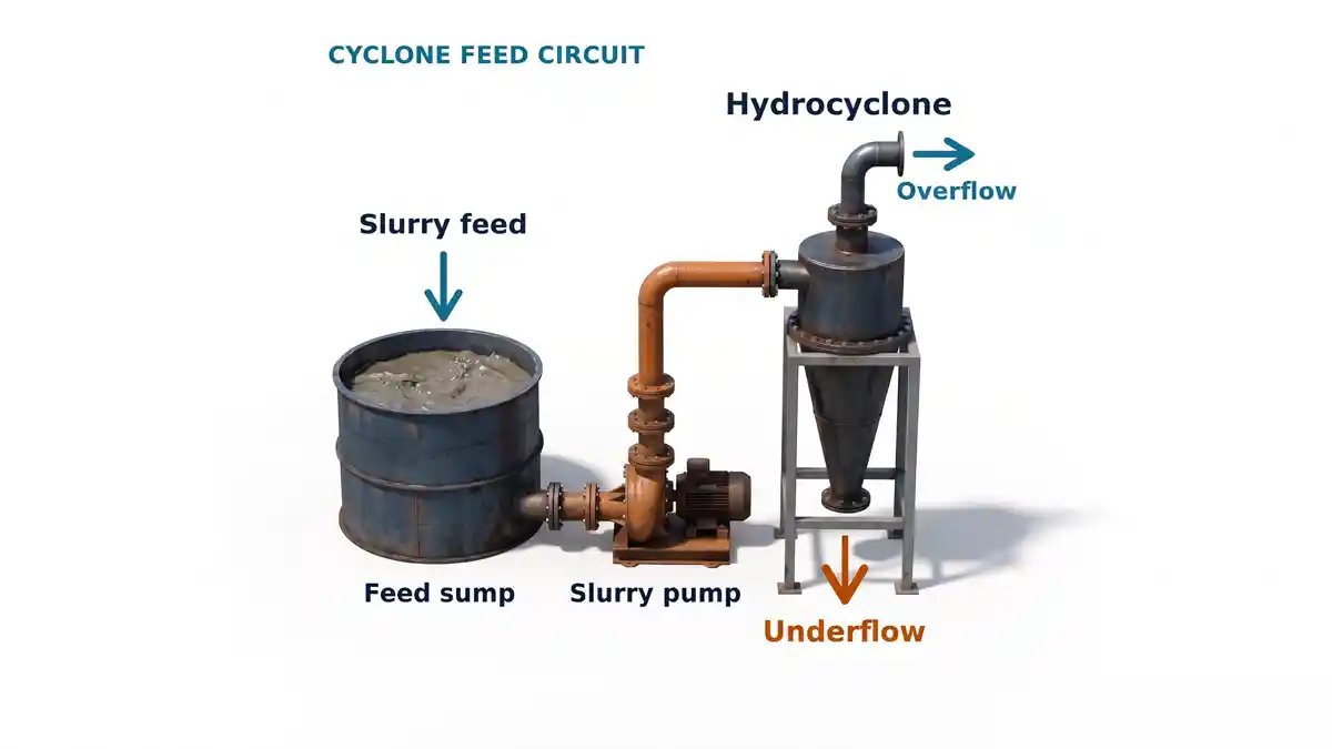
Stable Feed Starts Before the Cyclone
This guide explains how a hydrocyclone separates slurry, which feed conditions it needs, and how the feed pump and sump decide whether it gets them. It is written for mineral-processing and sand and aggregate plants that already run cyclones and want the pump side of the circuit to support them. For pumping in those plants, see sand and aggregate pumping. EDDY Pump does not make hydrocyclones, and the cyclone supplier's feed specification always comes first.
Hydrocyclones are also called cyclones, classifying cyclones or cyclone separators. This page covers classifier feed in mineral and aggregate processing. For drilling-mud transfer, see drilling-mud transfer pumps.
Hydrocyclone Separation Basics
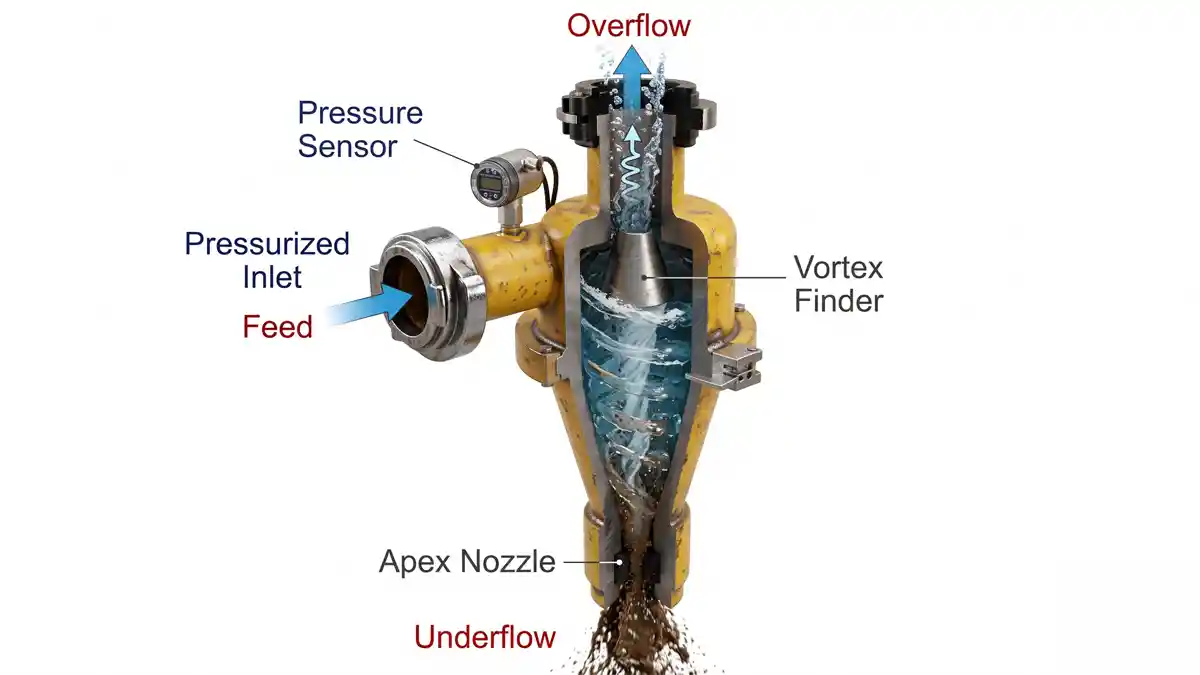
A hydrocyclone separator is a cone-shaped device that classifies solids by size and density using the centrifugal force of the slurry itself. Feed enters along the wall of the body, so its velocity sends it spiralling around the cylinder and cone. Larger or heavier particles are thrown toward the wall and leave through the bottom opening as underflow. Finer particles stay nearer the centre and leave through the top as overflow.
01
Feed inlet
the tangential entry that starts the spiral. Feed velocity and pressure at this point set how strong the separating force is.
02
Vortex finder
the pipe that extends below the feed inlet from the overflow outlet. Its diameter helps set the size at which separation occurs, and changing it means taking the cyclone out of service. If it is worn, damaged or too short, some feed can short-circuit straight to the overflow and carry coarse particles with it.
03
Apex
the underflow opening at the bottom of the cone. Its size sets how much solids can discharge. If it is too small for the load, the underflow thickens into a rope and coarse material reports to the overflow. If it is too large or worn, the underflow sprays out wide and wet and carries fine particles and water with it.
04
Air core
a column of air that forms along the centre of a working cyclone and is vented mainly through the apex. When the apex chokes, as in roping, the air core collapses and coarse material then reports to the overflow.
Roping and spraying are opposite apex problems. Roping is a thick, rope-like underflow and points to overload or an apex that is too small. Spraying is a wide, thin, wet umbrella of underflow and points to an apex that is too large or worn. The cyclone supplier sets the correction for either.
Because the cyclone itself has no moving parts, its performance is largely set by what the pump feeds it. That is why feed conditions matter.
Feed Flow, Pressure and Solids Concentration
A cyclone is designed around a feed flow, an inlet pressure and a solids concentration. Moving away from any of the three changes the separation, so a pump should be matched to the whole operating window, not one design point.
Ask the cyclone supplier for the feed envelope: the minimum and maximum flow, the inlet pressure window and the solids range. The pump has to cover all three.
- Flow: feed flow is set mainly by the inlet and vortex-finder size and by the inlet pressure, and it rises roughly with the square root of pressure. Flow and pressure therefore cannot be set independently. The apex limits how much solids can discharge, not how much volume the cyclone takes, so too much solids overloads the apex.
- Inlet pressure: within the supplier's pressure window, higher inlet pressure generally gives a finer cut and lower pressure a coarser one. Too little pressure leaves too little force to separate, and too much raises wear and the risk of overload. The cyclone supplier specifies the pressure window.
- Solids concentration: feed that is too dense can overload the apex, collapse the air core and produce a rope-like underflow. Too much dilution can send extra water to the underflow.
- Steady pressure: a cyclone classifies best with steady inlet pressure. A surging pump produces poor separation at both high and low pressure.
- Control: inlet pressure is the usual control signal. Operators adjust it with pump speed, sump level or make-up water for density, and the number of cyclones in service. Apex and vortex-finder sizes are changed at shutdowns, not as live controls.
Feed Sump and Air-Entry Considerations
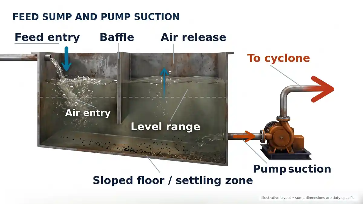
The sump, or pump box, sits between the process and the feed pump. Its design decides whether the pump sees a steady, air-free slurry or a variable one.
01
Air entry
if the sump runs low, the pump can draw in air, lose feed pressure and then recover with a pressure spike. Air bubbles reaching the pump suction also make inlet pressure fluctuate.
02
Settling in the sump
coarse particles can settle in a sump that allows it, then slump into the suction and overload the cyclone. Sump shape, slope and agitation are the usual remedies.
03
Level stability
a fluctuating sump level changes the pump's suction conditions and the pressure at the cyclone. Make-up water and a stable level target help.
04
Entry point and baffles
where feed enters the sump affects how much air is carried to the pump. Baffles or a different entry position can reduce it.
05
Suction head and submergence
keep enough liquid above the pump suction that the net positive suction head available (NPSHa) stays above what the pump needs, and that the level never drops far enough to form a vortex that draws in air. Set a minimum level and alarm it.
06
Floor shape and retention time
a sloped floor or agitation helps stop solids settling, and enough retention time smooths surges in the feed. Too much retention lets solids settle. Any slope or time figures come from the sump designer for the actual slurry.
07
De-aeration
froth and entrained air reduce the head a pump delivers and make inlet pressure unstable. Give air time to rise and escape before the suction, and where froth is heavy ask the supplier about de-aeration.
Wear and Changing Feed Conditions
Cyclone circuits are abrasive, and feed conditions rarely stay fixed. Both affect the pump and the cyclone, and the effects feed back on each other.
01
Pump wear
as any centrifugal slurry pump wears, it delivers less head and flow at a fixed speed. The cyclone then sees lower inlet pressure and its separation drifts. A variable speed drive can compensate within limits.
02
Cyclone wear
wear in the liner, apex or vortex finder changes the separation point. A worn or blocked apex also changes the pressure the pump works against.
03
Changing feed
ore or sand changes, tonnage swings, extra water from hoses and upstream circuit changes shift density and flow.
04
Blockages
a blocked apex or inlet raises pressure and sends material to the overflow. The pump sees a higher system resistance.
05
Records
log inlet pressure, pump speed and the time between wear-part changes on both the pump and the cyclone. A trend shows whether the cause is the pump, the cyclone or the feed.
When separation drifts, check the pump and sump before changing the cyclone settings.
Pump and System-Curve Selection
A feed pump for a cyclone has to deliver the cyclone's required flow at the head that produces the required inlet pressure, and to keep doing so as the circuit changes. The key tool is the system curve.
01
Convert pressure to head
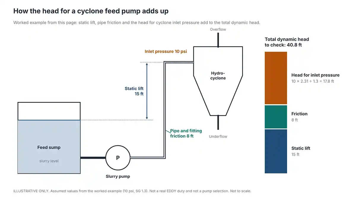
the cyclone supplier states inlet pressure. Head in feet = pressure in psi × 2.31 ÷ specific gravity of the slurry, so the result is feet of slurry. For the same pressure, a denser slurry needs less head in feet. A pump makes roughly the same head in feet at any density, so on a denser slurry it makes more pressure, and its absorbed power rises with specific gravity. Solids also reduce the head and efficiency a pump delivers compared with its clean-water curve.
02
Add the system losses
add static lift from the sump level to the cyclone inlet, and friction losses in the pipe and fittings, to the head needed at the inlet. Use slurry friction at the operating solids content, not the clean-water value. Keep line velocity above the settling (deposition) velocity at minimum flow, including at variable speed drive turndown, or solids will settle in the line.
03
Check the whole operating window
plot the pump curve over the system curve at the lowest and highest flow, density and sump level. Cyclone pressure drop rises roughly with the square of flow, so the system curve is steep, and changing the number of cyclones in service moves it. The pump has to give acceptable pressure and flow across the window.
04
Plan for control
a variable speed drive can adjust inlet pressure as feed conditions and wear change. It cannot make an under-rated pump suitable.
Worked Duty-Point Example
The example below shows the method with assumed numbers at one duty point. All heads are in feet. It is not a real EDDY duty and does not mean any EDDY pump suits it.
| Line | Value | Working |
|---|---|---|
| Cyclone inlet pressure (assumed) | 10 psi | Supplied by the cyclone supplier |
| Slurry specific gravity (assumed) | 1.3 | From density measurement |
| Head for inlet pressure | 17.8 ft | 10 × 2.31 ÷ 1.3 |
| Static lift, sump level to inlet (assumed) | 15 ft | Measured on the layout |
| Slurry friction in pipe and fittings (assumed) | 8 ft | From the line calculation at the operating solids content |
| Total dynamic head of slurry | 40.8 ft of slurry | 17.8 + 15 + 8 |
| Head ratio for solids (assumed) | 0.90 | Varies with particle size and solids concentration |
| Equivalent clean-water head to compare with a pump curve | 45.3 ft | 40.8 ÷ 0.90 |
Compare the clean-water equivalent head, at the required flow and across the density and sump-level range, with the pump curve. Do not rely on a single point.
EDDY process pumps are slurry transfer pumps with large internal clearances, suited to abrasive, high-solids slurry. Whether a given model meets a cyclone's feed envelope depends on the flow, head and solids at that site, so confirm it against the supplier's full feed specification. EDDY engineering reviews the duty. EDDY does not guarantee separation efficiency, d50 or sharpness of cut. The pump's job is stable flow and pressure, and the cyclone and its operating conditions decide the separation.
Questions for the Cyclone and Pump Suppliers
Ask both suppliers the same questions so the cyclone and the pump are specified against one set of numbers.
| Topic | Ask the Cyclone Supplier | Ask the Pump Supplier |
|---|---|---|
| Flow | What are the minimum and maximum feed flows for this cyclone or cluster? | Does the pump cover that range at the required head? |
| Pressure | What is the inlet pressure window? | What head and speed deliver that pressure at my slurry density? |
| Solids | What feed density and top particle size are allowed? | What solids concentration and particle size can the pump handle? |
| Variation | How much feed variation can the cyclone tolerate? | How does the pump perform across the density and flow range? |
| Wear | What is the expected wear-part life at my duty? | What wear parts does the pump have and how are they replaced? |
| Control | What is the pressure control strategy and instrument location? | Can the pump run on a variable speed drive over this range? |
| Sump | What does the cyclone need from the sump? | What suction and sump conditions does the pump need? |
| Documentation | Which drawings and feed data are issued? | Which curves and datasheets are issued for my duty? |
| Power | What pressure and flow does the cluster need at duty? | What is the absorbed power and efficiency at my duty and density? |
Hydrocyclone Feed Pump FAQs
How does a hydrocyclone separator work?
Slurry enters the cyclone along its wall and spirals around the body and cone. Centrifugal force pushes larger or heavier particles to the wall, where they leave through the apex as underflow. Finer particles stay near the centre and leave through the vortex finder as overflow. The cyclone has no moving parts and relies on the feed pump for its energy.
What is a hydrocyclone used for?
It is used to classify slurry by particle size and density, for example to separate fines from coarse solids in mineral processing, or sand from water in aggregate washing. The cyclone supplier sets the cut for each application.
What feed pressure does a hydrocyclone need?
It depends on the cyclone model and the separation required, so use the cyclone supplier's specified inlet pressure window. Within that window, higher pressure generally gives a finer cut and lower pressure a coarser one. Below the window there can be too little force to separate, and above it wear and the risk of overload rise.
Why does a hydrocyclone need steady feed?
Separation depends on stable inlet pressure and flow. A surging pump, an emptying sump or air in the feed makes pressure fluctuate, and separation gets worse at both high and low pressure.
What causes roping in a hydrocyclone?
Roping is a thick, rope-like underflow. It is usually caused by feed that is too dense or an apex that is too small for the load. Follow the cyclone supplier's guidance. Reducing the solids rate or fitting a larger apex are the usual remedies. The opposite problem, spraying, points to an apex that is too large or worn.
How should a cyclone feed sump be designed?
It should hold a stable level, avoid letting coarse solids settle and slump into the pump suction, and keep air out of the feed. Sump slope, agitation, baffles and the feed entry point all affect this.
Can a slurry pump be used as a hydrocyclone feed pump?
Yes, if its flow, head and solids handling cover the cyclone's feed envelope across the whole operating window, including wear and density changes. Check the pump curve against the system curve and the cyclone supplier's specification. EDDY engineering can review the duty.
LET’S PUT YOUR PROJECT IN MOTION
Tough material?
Bring it to EDDY.
Tell us what you’re pumping, where it needs to go, and what your
operation needs to achieve.
Talk it through
with our team.
Equipment selection, project planning, or an existing pump—we’ll help you find the right next step.
CALL SALES & ENGINEERING
+1 619-404-1916
EMAIL YOUR PROJECT DETAILS
info@eddypump.com