
Pipe Friction Loss & Pressure Drop Calculator
Estimate straight-pipe and specified fitting losses using Darcy–Weisbach. Enter actual pipe ID, operating flow, roughness, and kinematic viscosity to review head loss, pressure drop, and flow regime.
CALCULATE YOUR OPERATING VALUES
See what the pipeline adds to the duty.
Estimate straight-pipe and specified fitting losses using Darcy–Weisbach. Enter actual pipe ID, operating flow, roughness, and kinematic viscosity to review head loss, pressure drop, and flow regime.
For full circular pipe and incompressible Newtonian liquids. Does not include elevation, terminal pressure, pump performance, non-Newtonian behavior, or heterogeneous-slurry corrections.
UNDERSTAND THE NUMBERS
Friction loss depends on more than pipe length.
A pipe friction loss calculator estimates the energy dissipated as liquid moves through a line. For a full circular pipe, Darcy–Weisbach relates that loss to length, inside diameter, average velocity, and a friction factor. This tool also adds a specified total fitting-loss coefficient and converts the resulting head loss to pressure drop.
The friction factor depends on Reynolds number and relative wall roughness. Reynolds number combines velocity, diameter, and kinematic viscosity; relative roughness compares absolute wall roughness with the pipe’s internal diameter. These inputs distinguish a smooth water line from a rougher line or a more viscous liquid service.
This tool models incompressible Newtonian liquids. For heterogeneous slurry, fibrous material, yield-stress fluids, or strongly non-Newtonian mixtures, the calculated liquid loss is only a reference. Entering a higher specific gravity changes pressure conversion here; it does not apply a slurry-friction correction or establish a transport velocity.
METHOD & UNITS
The relationships behind the result.
The calculator converts inputs to SI units, performs the calculation with unrounded values, and converts the result for display.
PIPE FRICTION
hf = f × (L/D) × v²/2g
The factor f is the Darcy friction factor. Length and diameter must use the same units.
FITTING LOSSES
hK = ΣK × v²/2g
The entered coefficients must refer to velocity in the same pipe bore used by the calculation.
PRESSURE DROP
ΔP = ρg × (hf + hK)
Convert the calculated loss head to pressure using the entered specific gravity.
FROM INPUT TO ANSWER
Four steps to a useful result.
01
Define the line
Enter actual ID and straight-pipe length. Calculate different-diameter sections separately.
02
Set the liquid and flow
Enter operating flow, kinematic viscosity at temperature, and specific gravity.
03
Review roughness and fittings
Use a representative wall roughness and verified total K. Do not count the same fitting twice.
04
Read the full result
Check Reynolds number, flow regime, Darcy factor, straight-pipe loss, fitting loss, and total pressure drop.
WORKED EXAMPLE
A 6-inch bore at 500 US GPM.
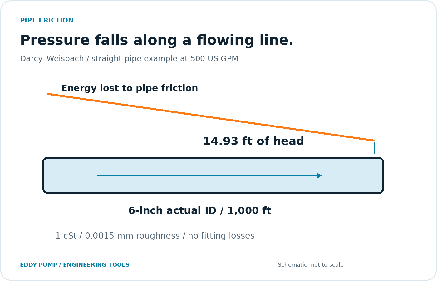
For 1,000 feet of straight pipe with a 6.000-inch ID, 500 US GPM gives an average velocity of about 5.6736 ft/s. With kinematic viscosity of 1 cSt and absolute roughness of 0.0015 mm, Reynolds number is approximately 263,546, in the turbulent range.
The Colebrook solution gives a Darcy friction factor of about 0.014919. With total K = 0, straight-pipe friction loss is approximately 14.9266 feet, or 4.5496 meters. At SG 1.00 this corresponds to about 6.4711 psi of pressure drop.
Adding fitting coefficients increases the local-loss component. Adding elevation does not change this friction calculation; elevation belongs in the broader system-head balance. A pump must be evaluated against the combined duty, not only the line loss shown here.
WORKED EXAMPLE RESULT
14.93 ft
4.5496 m friction head / SG 1.00
500 US GPM · 6-inch actual ID · 1,000 ft · 1 cSt · 0.0015 mm roughness · K = 0.
A smaller bore costs far more than a longer run
In Darcy-Weisbach, straight-pipe loss grows with the square of flow and falls with roughly the fifth power of inside diameter. That is why a small change in bore matters more than the same change in length.
| Change, all else equal | Approximate change in straight-pipe head loss |
|---|---|
| Pipe length +10% | +10% |
| Pipe length doubled | 2× |
| Flow +10% | +21% |
| Flow doubled | about 4× |
| Inside diameter −10% | +69% |
| Inside diameter −20% | about 3× |
+69%
friction loss from a 10% smaller inside diameter. Check wear, lining thickness and deposits before trusting a nominal bore.
Approximation that holds the Darcy friction factor constant. The calculator re-solves the friction factor for every input, so exact results differ slightly. Roughness and viscosity act through that factor and usually move the result less than the terms above.
PLAN THE COMPLETE SYSTEM
Build a defensible pipeline estimate.
Actual internal condition
Use current ID and a roughness appropriate to the wall, lining, wear, and deposits. Material presets are starting values, not a substitute for inspection or manufacturer data.
Flow regime
Below Reynolds number 2,300 the tool uses f = 64/Re. Above 4,000 it solves Colebrook. In between, it reports a transitional estimate and flags the uncertainty.
Complete system head
Add static elevation and terminal-pressure requirements separately. Include losses through equipment and other line sections before comparing the total duty with a pump curve.
Friction loss is one step in a pump duty
Use the results from this page as the friction input to the rest of the duty.
01
Flow and velocity
Confirm the velocity for your flow and actual inside diameter.
02 YOU ARE HERE
Friction loss
Get head loss and pressure drop for each pipe section and for your fittings.
03
Total dynamic head
Add static elevation, fittings and velocity head to build the duty head.
04
Suction and power
Check suction conditions and then power.
Ready to compare the duty with a pump curve? Request a pump duty review →
COMMON QUESTIONS
Frequently asked questions
Which friction method does this calculator use?
It uses Darcy–Weisbach. For laminar flow below Reynolds number 2,300 it uses f = 64/Re. At Reynolds number 4,000 and above it solves the Colebrook equation iteratively. Transitional values are interpolated between those endpoints and displayed with an estimate warning.
Is the friction factor Darcy or Fanning?
The displayed factor is the Darcy friction factor. For the same flow condition, it is four times the Fanning factor. Using a Fanning value directly in the Darcy–Weisbach equation without conversion would understate straight-pipe loss by a factor of four.
How do I include elbows and valves?
Add their verified loss coefficients as total ΣK, using coefficients referenced to velocity in the entered pipe diameter. Valve opening and fitting geometry matter. If you already included a fitting as equivalent pipe length, do not also include the same loss in ΣK.
Can this calculate slurry friction loss?
It does not implement heterogeneous-slurry or non-Newtonian corrections. A density change alone is insufficient to describe those effects. Use the result as a Newtonian-liquid reference and evaluate actual particle distribution, concentration, rheology, and transport conditions with an appropriate slurry model.
Why is inside diameter so important?
Diameter changes both flow velocity and the length-to-diameter term. At fixed flow, a smaller bore raises velocity sharply and can substantially increase head loss. Lining, deposits, and a change in pipe schedule can therefore alter the duty even when the nominal size stays the same.
Does this include static lift?
No. It calculates friction and specified fitting losses. Static elevation, pressure differences between the system boundaries, and velocity-head differences belong in the total system-head calculation. Keeping them separate helps prevent double counting.
Which viscosity should I enter?
Enter kinematic viscosity in cSt or m²/s at the operating temperature. One cSt equals 1 mm²/s. If your data gives dynamic viscosity, convert it with density before using the tool. A non-Newtonian fluid may not be represented adequately by one constant viscosity value.
Why does zero flow return zero head loss?
Within this model, pipe and fitting losses disappear when velocity is zero. That does not mean the system has zero static head or zero pressure. A stationary liquid can still impose hydrostatic loads that must be considered separately.
Calculation method and references
Calculation methods use the stated geometric or hydraulic relationships. Inputs and outputs are rounded for display only; the calculator uses unrounded converted values internally.
→ Hydraulic Institute: pipe-friction equations and flow regimes
→ Hydraulic Institute: friction calculator assumptions
→ KSB: head loss, roughness, and fitting coefficients