
Red Mud Pumping White Paper


Mt Rosser Pond
Remediation Project – Mud Pump Trials – Findings
DOCUMENT CONTROL SHEET
| Client | Rio Tinto Alcan | |||||
| Project Title | Rio Tinto Alcan Excluded Assets Remediation | |||||
| Document Title | Mud Pump trial – Findings | |||||
| Document No. | MDE0182RP0038WPR | |||||
| This Document Comprises | DCS | TOC | Text | List of Tables | List of Figures | No. of
Appendices |
| 1 | 1 | 16 | 0 | – | – | |
| Rev. | Status | Author(s) | Reviewed By | Approved By | Office of Origin | Issue Date |
| D01 | Draft | W Orsmond | C Masson, R Tapp | West Pier | 22 Oct ‘11 | |
| F01 | Final | W Orsmond | C Masson | W Orsmond | West Pier | 15 Nov ‘11 |
1 INTRODUCTION
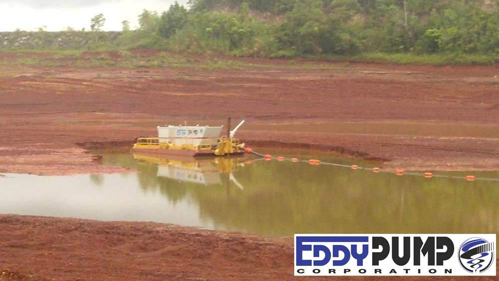
Mt Rosser Pond is a bauxite residue (red mud) tailings dam situated within the Diablo Mountains just north of the town of Ewerton in Jamaica.
 Figure 1.1
The “pond” is actually a man made dam which covers an area of about 40ha and has rockfill embankments of up to 53m high along the southern side that forms the impoundment. It initially constructed in 1959 to act as a tailings pond to take the bauxite residue (red mud) from the Ewarton Plant situated about 5km away and 300m lower. The red mud was pumped as a slurry comprising about 20% solids to the pond over a period of about 32 years up to 1991 when the pond was replaced by the Charlemount Mud Stacking and Drying Facility. During this period the pond embankments (referred to as dams), were raised up to 7 times providing a final crest elevation of 472m. The pond was however never filled to its final design capacity and the mud beach level remained at about 469m and the central area about 458m leaving a concave depression which held about 1.4mil m3 of water with elevated pH and some caustic content.
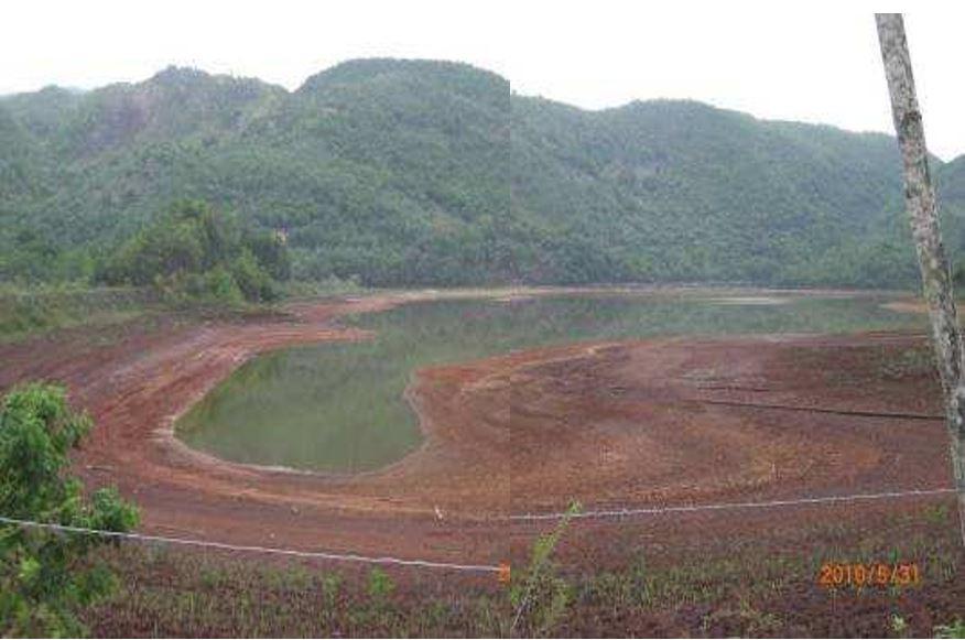 Photo 1.1: Mt Rosser Pond looking from the south-east corner to the north-west
The remediation plan for the pond includes the removal of the ponded water and then the regrading of the mud surface to be free draining so that it can be stabilised and vegetated. About 500,000 m3 of mud will need to be moved over a distance of up to 1km in order to create the required profile. Due to the very soft nature of the surface muds (shear strength of less than 3kPa) its bearing capacity is less than 20kPa hence it is not accessible using even modified earthworks equipment. In addition, the muds are thyrotrophic and under any vibration or shear loading, rapidly liquefy resulting in significant reduction in shear strength and loss of bearing capacity. Using conventional earthmoving equipment would therefore require extensive “floating” haul roads with a high risk of machinery getting stuck or entire plant loss and risk to personnel. It was therefore decided to investigate the possibility of pumping the in-situ red mud.
A mud pumping trial was undertaken to assess the feasibility of using this technique to do the bulk mud moving. Pumping red mud is not unusual and the muds were initially pumped up to Mt Rosser Pond. However, the muds are usually pumped at a solids content of 30% or less. Once deposited, they can take years to reconsolidate and firm up sufficiently to allow access for light earthworks and agricultural plant.
In addition to the mud pumping, the trial included infilling three small scale geotubes to assess their performance as these may be needed as part of the regrading works.
Project reference: AuM 0894 Jamaica. HSEQ Work Package ref: JWP# 11001
1.1 AIM OF THE TRIAL
The main aim of the pump trial was to determine if the muds could be pumped in their insitu state, and if not, what amount of water is required and how the variations in water content affect pump rates.
Linked with this was to:
- gain an appreciation of the difficulties in pumping in these conditions
- get an understanding of the behaviour of the muds surrounding the pump area.
- assess how the muds behaved once deposited and how they react when deposited into water.
For the geotubes, the main aim was to assess how the tubes contained the pumped muds and how they reacted with time.
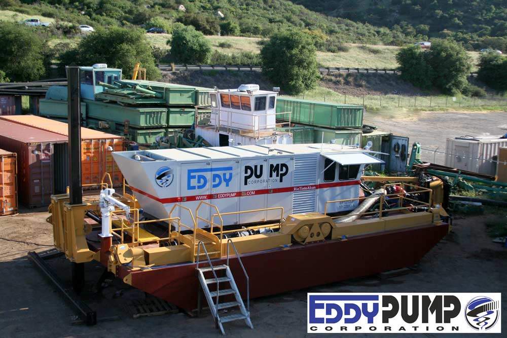
2 EQUIPMENT USED
The mud pumping trial was undertaken using a 4” EDDY Pump. This pump was recommended due to its ability to handle variable solids and robust operating mechanism. The pump unit incorporated a hydraulic drive and cutter head. The unit was mounted onto the boom of a JCB 220 excavator which also supplied the hydraulic feed to power the pump for the required range of 30-40 GPM at 3,500 to 4,000 psi (2428MPa). The cutter head was powered by a standalone hydraulic power unit capable of providing the required 30gpm at 200psi (1.9 l/s at 13.8MPa). If mounted on a 30-ton excavator with a System 14 hydraulic system and dual auxiliary feeds to the boom, all necessary hydraulic power for the pump and cutter head can be supplied by the excavator. This equipment was however not available at the time in Jamaica.
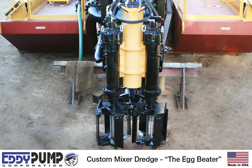
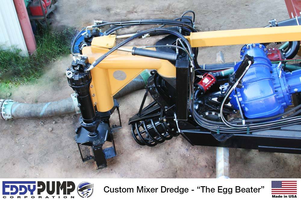
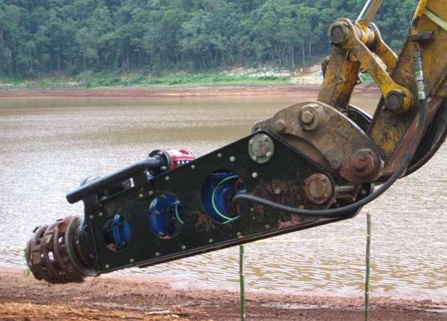 PHOTO 3.1: EDDY Pump in Excavator Attachment
In addition to the pump mounted on the excavator a Long Reach excavator (CAT 325) was used to move muds towards the cutter head but also to loosen up the muds and mix in additional water to facilitate pumping. Water was added by pumping it directly from the pond using a 3” diesel water pump.
Prior to pumping the muds, the mud pump would operate in recirculation mode in order to prime the pump. When in recirculation (re-circ) mode, the material pumped would be diverted to a short discharge pipe mounted on the pump directed back parallel to the cutter head. This action would help agitate and stir the muds.
 Photo 3.2: CAT 325 Long reach (60ft boom) and JCB220 with Eddy mud pump.
The geotubes for the trials were 6m long and 1m high (filled) and were supplied by Tencate. The tubes were made from a woven polyester – GT1000M and had a central top filling point. A set of small bags with a polymer test set was also provided but this was not tried during this occasion.
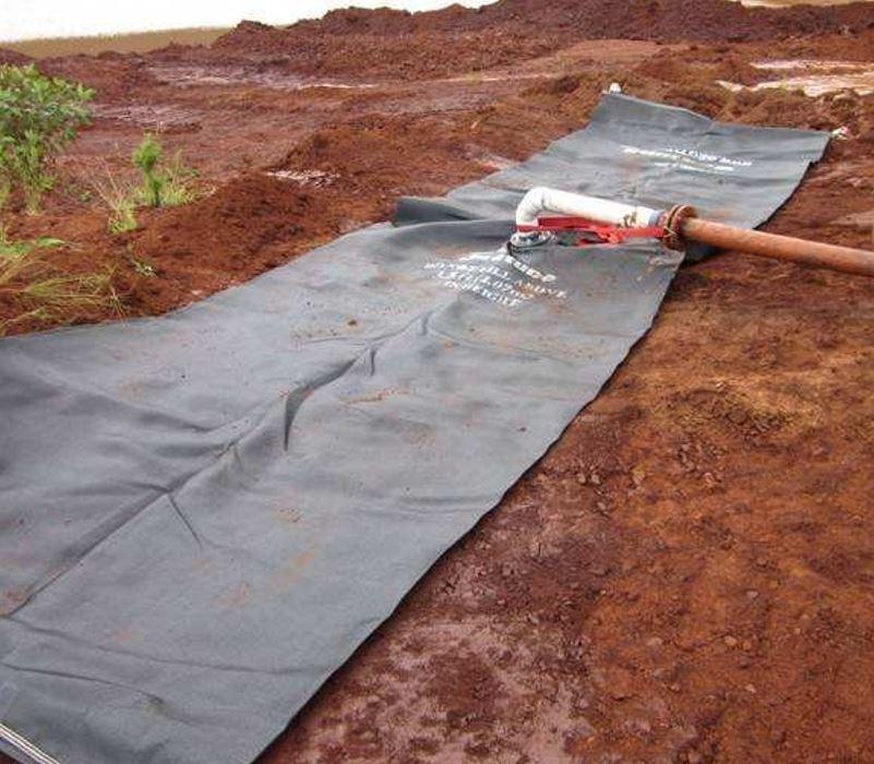 Photo 3.2: Geotube prior to filling
3 MATERIAL PROPERTIES
A geotechnical soils investigation was undertaken on the muds within Mt Rosser pond in 2004. It showed the material to be predominantly clayey silt with approximately 13% sand, 29% clay and 58% silt using conventional sieve analysis and hydrometer. Atterberg limits indicate that the material is an intermediate to high plasticity clay. The muds do however vary across the lake and also vertically. This is mainly as a consequence of the deposition process and discharge location. Close to the discharge location the courser materials would settle out first and the finer materials would disperse furthest and to the opposite end of the pond. The results are presented in figure 4.1.
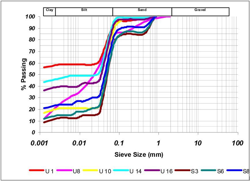 Figure 4.1: Grading analysis (conventional soil mechanics method, 2004 SI)
Earlier this year, additional mud samples were tested as it was evident that standard soil mechanics tests did not provide an accurate assessment of this fine material. This was particularly evident in tests done with dry sieving which shows the material as well-graded sand (see results for samples 5300, 5301, 5302 on figure 4.2). When dispersed in water, even with an agent, the ‘yield-pseudo-plastic’ rheology of the muds appeared to affect the hydrometer results with large variations between tests (see results of samples PFT4&5 taken during mud pumping trials on figure 4.2).
The additional testing comprised of undertaking gradings using a Laser Particle Analyzer. The results indicated that the muds are predominantly Silt although the silt % varied from 30% to 80% with the material being either more sandy or more clayey (up to 15% clay). See results of samples ending in “L” on figure 4.2 below.
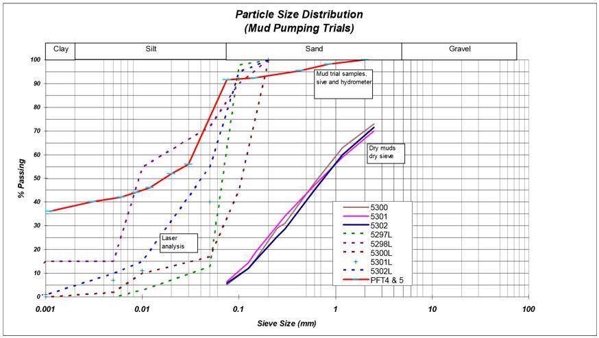 Figure 4.2: Grading analysis of dry muds using dry sieving (5300-2), wet muds using sieving & hydrometer (PFT) and laser analysis (L suffex).
Moisture content tests on the muds taken from within the mud pond but below the ponded water ranged from 100% to 150% (50% to 40% solids). The muds at the pump test location were 137% (42% solids).
Shear strength was generally very low ranging from 1kPa to 6kPa increasing with depth. Dynamic probes previously undertaken indicated that the muds are “very soft” to 5m increasing in strength slightly to “soft” at a depth of 9m after which they increase to firm becoming stiff.
The pH of the muds ranged from 10.3 to 11.7, (ave 11.2). Previous testing indicated that the surface muds have the lower pH although once through the crust, the pH tends to be higher. When doing the trials, the muds up to a depth of about 2.5m was intermixed, hence any stratification in pH could not be determined.
4 FINDINGS
4.1 MUD PUMPING
Initially, pumping was problematic mainly due to the excavator being underpowered. This was diagnosed as a hydraulic pump problem and the excavator was replaced. The cutter head (which also acts to protect the intake) tended to blind with mud (Photo 5.1) and was also not providing enough agitation to liquefy the muds. This was partly resolved by adding “stirrers” (2 steel loops welded either side) to the rotating cutter head and also a “comb” (Photo 5.2) to keep the gaps within the cutter head open.
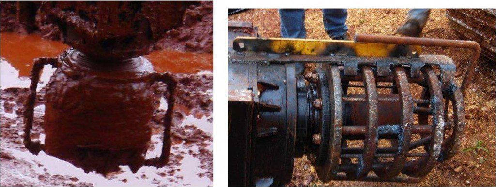 Photo 5.1: Cutter head blinded with mud Photo 5.2: Cutter Head With Comb added
Mud pumping rates varied from 21 l/s to 52 l/s (332 – 824gpm) and it was clearly visible that the more liquid the muds were the higher the pump rate was. Samples were taken at different discharge rates and moisture content and percent solids determined by laboratory testing. The results are plotted in Figure 5.1 and although scattered, do give an indication of the effects of solids content on flow rates. The natural moisture content of the muds (insitu) at the test location was 137%, or 42% solids. This is shown in Figure 5.1 as a vertical line. Pumping muds close to the percent solids was achieved although flow rates were low.
As mentioned previously, the long reach excavator was used to loosen up the muds. Water was pumped from the pond using a 3” pump into the excavation and the long reach would then work the muds to mix the water in. The mud pump would then be used in recirculation mode to further mix the muds into a more consistent state. Even with this mixing and agitation, the water tended to concentrate on the surface. This aided the initial process of priming the pump and once primed thicker muds at 1m to 2m below the surface could be pumped. However, it was found that the deeper muds tended to be lumpy and this would significantly reduce or stop the flow requiring the pump to be lifted into thinner muds or having to go back into re-circ mode or having to fully re-prime. The pump discharge was therefore very inconsistent as the suction intake position constantly needed adjustment in an attempt to get adequate discharge but also pump the thickest muds possible.
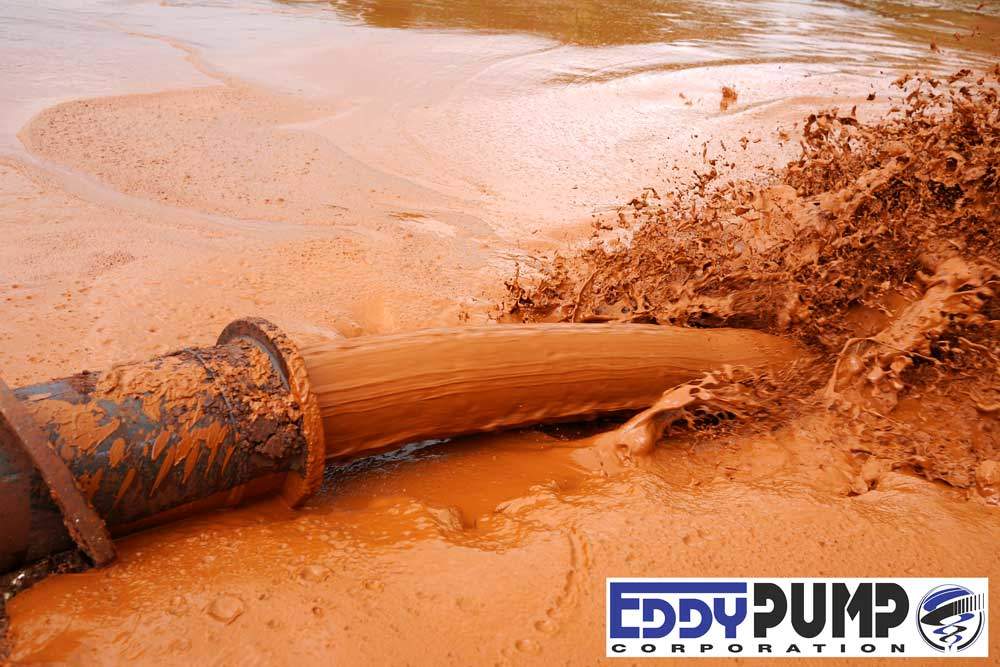
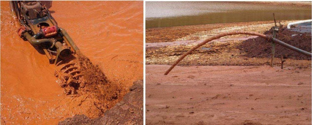 Photo 5.3: Mud pump in re-circ / priming mode Photo 5.4: Discharge of muds (±30l/s, ±37% solids)
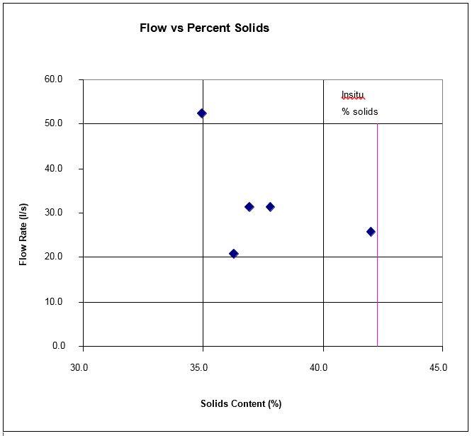 Figure 5.1: Graph of Flow rate at various solids content
Discharge of the pumped muds was through 30m of flexible hose then 60m of 4” HDPE pipe which had an internal diameter of about 87mm (3.5”). The muds were discharged onto the original mud beach which lies at a gradient of about 9%. On deposition the muds slowly flowed down gradient. At times the flow would stop and the muds would build up then flow again in a wave motion. The natural angle of repose would therefore be a few degrees less than this – probably 5% to 6%.
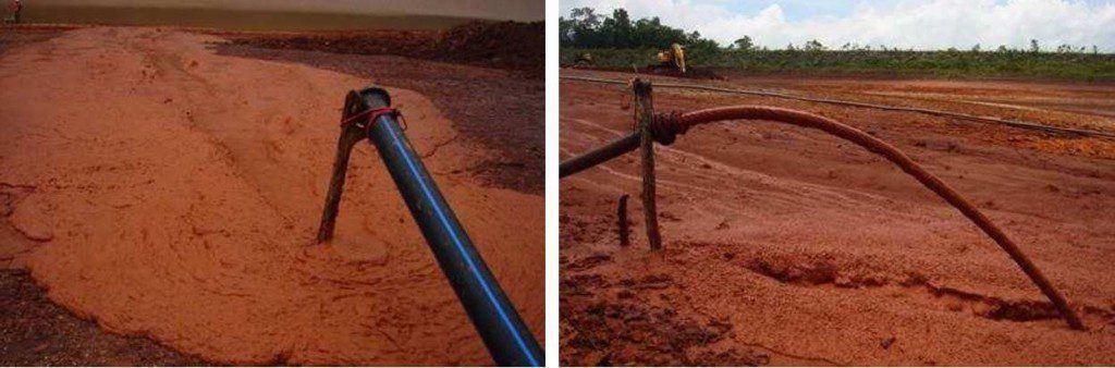 Photo 5.5: Mud discharge point Photo 5.6: Muds being discharged
Although the muds have very low shear strength, and on agitation liquefy, the sides of the excavation had sufficient strength to stand about 2m near vertical. Even overnight, there was limited slumping and the bank could be undermined by about 0.5m with the cutter head/agitator before collapsing.
On termination of pumping, in order to flush the pipeline, thin watery muds were pumped until the line was clear. A “T” valve system was then used to connect the 3” water pump line and this was then used to flush the pipe with water.
4.2 GEOTUBES
Three geotubes (1m x 6m) were filled with red muds pumped using the 4” Eddy pump. Fill rates were about 30 to 40l/s although it was difficult to assess as the flow and mud consistence was not visible.
Tube 1 was filled initially with more runny mud and then thicker muds as the pump operator got a better feel for conditions. The tube was filled until firm. The second tube was filled with thicker muds and filling continued until the tube was taut. These two tubes were positioned on the sloping beach in order to form a small “U” impoundment area that would later be filled with pumped muds. Although the area was prepared, the sloping ground caused the first tube to rotate through about 20 degrees. The tube was staked and the downslope side backfilled. A more defined bed was created for the second tube and the same rotational issue was limited. The two filled tubes with the ponded mud are shown in Photos 5.7 and 5.8. Other than a small leak at the contact between the two geotubes, the ponding of the muds was successful.
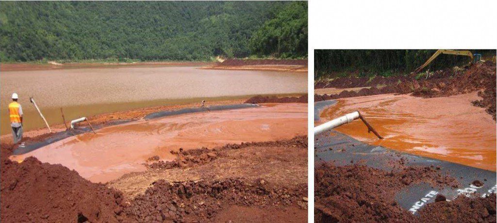 Photo 5.7: Two geo tubes forming the bund of the trial pond Photo 5.8: Muds after pumping are liquid
The third tube was positioned on level ground. It was filled with medium runny (but consistent thickness) muds and was filled until the tube was taut.
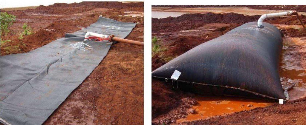 Photo 5.10: Geotube prior to filling Photo 5.11: Geotube filled taut – note seepage /bleeding
In all three cases, there was very little mud loss or seepage from the tubes. When stood on, some red water would squeeze out around the pressure area. Once filled taut, the entire bag would have small red water droplets form on the outside (visible in Photo 5.11) , but the seepage was in general nominal.
The tubes have been monitored and the most recent photo’s taken on 10 October 2011 (6 weeks after filling) show how the tubes have reduced in volume due to the dewatering of the contained muds. Volume loss is estimated to be around 30%. The anticipated moisture content would therefore be about 90% and the solids around 53%.
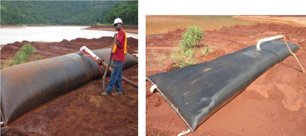 Photo 5.12: Geotube #3 filled to capacity Photo 5.13: Geotube #3after 6 weeks
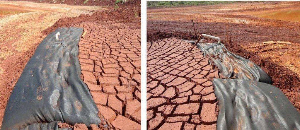 Photo 5.14: Geotube #4 after 6 weeks Photo 5.15: Geotube #1 after 6 weeks
The muds pumped into the trial pond behind the geotubes were medium thick to thick, probably in the order of 37 – 40% solids. After 6 weeks the mud has not only firmed-up but had dried out significantly with wide and deep surface cracks as are evident in Photo 5.14 and 5.15.
Monitoring of the tubes and trial pond is ongoing.
6 NEXT STEPS
The trial has demonstrated that:
- The muds can be pumped although water needed to be added to achieve “normal” discharge volumes.
- The muds can be pumped at close to their insitu moisture content and most likely at their in-situ moisture content if they were agitated more and the pipeline system was designed to reduce friction losses.
- The pump needs a priming method as the muds are too thick to allow it to prime.
- Access on the mud surface is problematic and will be very difficult on pumped mud.
Therefore, if pumping is to be used as the main method of moving the muds to regrade the pond, then the pump setup needs as a minimum the following:
- Be able to access the mud surface and move around efficiently and safely. The suggestion is to have the pump mounted on a pontoon that is positioned using high strength rope (dynema) or steel cable. The pump system should be remotely controlled as this would limit regular movement of personnel on the muds.
- Have a priming system that does not require water ponded on the surface.
- Be able to agitate the muds around the suction head to completely liquefy them.
- Have sufficient power and volume capacity to pump the muds at close to or at in-situ moisture content and discharge them about 1000m through a flexible pipeline.
It was also evident from the trials that the muds do not slump and flow readily. It will therefore be necessary to have an amphibious excavator to loosen up the muds in the area around the pump head. This weakened and more liquid mud would also aid the movement of the pump pontoon. To also limit the amount of movement the pontoon will need to do, the amphibious excavator could also move muds towards the pump location.
7 PROGRAM
Using the capacity of the 4” mud pump, mud moving would take about 1.5 to 2 years, the pump will however need to be more suited to the task. A target period of 1 year however seems reasonable. However, prior to this, equipment will need to be procured and imported into Jamaica. The 6 and 10 inch Excavator Dredge Pump Attachments are also being considered as an option for higher GMP and a more aggressive completion timeline. A preliminary programme is as follows:
Dec 2011 – March 2012 : Procure Pump and Amphibious excavator. Get pontoon fabricated in Jamaica
April 2012 – May 2012 : Import plant and establish on-site
June 2012 – June 2013 : Mud pumping and bulk earthworks
July 2013 – July 2014 : surface stabilisation and start vegetation.[/et_pb_text]
Job Specific Questions? Call Us Today
Talk with our engineering department and we can match the right equipment for your dredging project.